Sources : https://www.cpttransmission.com/tech_tvcable.htm
T.V. Cable Adjustment
WARNING: PERMANENT DAMAGE WILL OCCUR IF THE T.V. CABLE IS NOT ADJUSTED OR HOOKED UP.
THE DAMAGE WILL OCCUR WITHIN A FEW FEET OF DRIVING THE VEHICLE!
The TV cable on the 700R4 and 200-4R transmissions controls line pressure, shift points, shift feel, part throttle downshifts, and detent (full throttle) downshifts. So if the TV cable is not adjusted properly, it can cause numerous transmission problems.
The TV cable is connected to and operates the throttle lever, and bracket assembly mounted on the valve body. The function of the throttle lever and bracket assembly I to transfer the movements of the throttle plate in the carburetor to the TV plunger in the valve body. This causes TV pressure and line pressure to increase according to throttle opening and also controls modulated and detent downshifts. The proper adjustment of the TV cable is based on the TV plunger being fully depressed with the engine at wide-open throttle (see figure 9). When the TV cable is properly adjusted the movement of the TV plunger in the valve body is calibrated to the movement of the fuel delivery system. This means the transmission will always have the correct oil pressure and shift feel regardless of engine torque. Simply put, due to this calibration, engine torque and transmission line pressure/shift feel will always be in balance.
If a change is made, such as a different carburetor installed, the change in geometry could disrupt this balance and proper adjustment may never be achieved.
Many people try to defeat the self-adjusting TV cable and tailor shift points of shift feel. However, remember that on the 700R4 and 2004R Transmission the TV cable controls both shift feel (clutch apply pressure) and shift points, you therefore cannot alter one without altering the other.
Let’s discuss briefly what happens when someone tailors the TV cable:
Shortening the Cable : If you shorten the cable (move it towards the adjuster tab), this raises both one pressure and shift point. However, when the drive performs a full throttle downshift the TV cable will readjust to its approximate normal position.
Lengthening the Cable : If you lengthen the valve, this lowers both line pressure and shift points. Under this condition, the TV cable will not readjust during a full throttle downshift. What you have effectively done is allowed the engine torque to be ahead of transmission line pressure and shift points. Operating the vehicle under this condition will cause premature clutch wear and transmission malfunction.
DIAGNOSIS
A TV cable that is sticky; misadjusted, broken or incorrect for the vehicle can cause various transmission malfunctions. A sticky or binding TV cable can result in delayed or full throttle upshifts (figure 9). At other times, the TV cable may stick or bind only when the engine off. To check for this problem, run the engine at idle with the transmission selector in neutral and the parking brake set. Pull the end of the TV cable located on the throttle linkage, through its full range of travel, then release it. It should return to rest against the cable terminal (figure 10), it may be caused by one or more of the following conditions:
1. A sharply bent or damaged TV cable hosing. To correct this problem, try rerouting the cable. If this doesn’t cure the problem, replace the cable.
2. A burr or sharp end on the TV link. This condition would cause the link to drag in the TV cable housing. You can correct this situation by filing the end smooth but Do Not shorten the link.
3. Misalignment of the throttle lever and bracket assembly on the valve body. Correct the alignment and torque the bolts to the proper specifications as noted in your service manual.
4. A bent TV link. Straighten or replace the link as required.
5. A binding or damaged throttle lever and bracket assembly. Straighten or replace the assembly as required.
6. An unhooked or damaged throttle lever spring. Reconnect the spring if it is unhooked. If it is damaged, replace the throttle lever and bracket assembly.
7. An incorrectly adjusted TV cable. (A) If the cable is adjusted too long, one of the following conditions may result: (1) early shifts, slipping, and/or no detent downshifts; (2) low line pressure. (B) If the cable is adjusted shore, or not hooked up at all, line pressure and shift points will rise and full throttle operation may not be possible.
ADJUSTMENTS
Before adjusting the TV cable, check the following:
1. Transmission oil level. Correct if necessary.
2. Proper engine operation. This can cause problems similar to a malfunctioning transmission.
3. Dragging brakes. This can cause detract from vehicle performance and cause transmission malfunction.
4. Check the TV cable to insure that it is the right part for the vehicle.
5. Check the cable to insure that it is properly connected at the transmission.
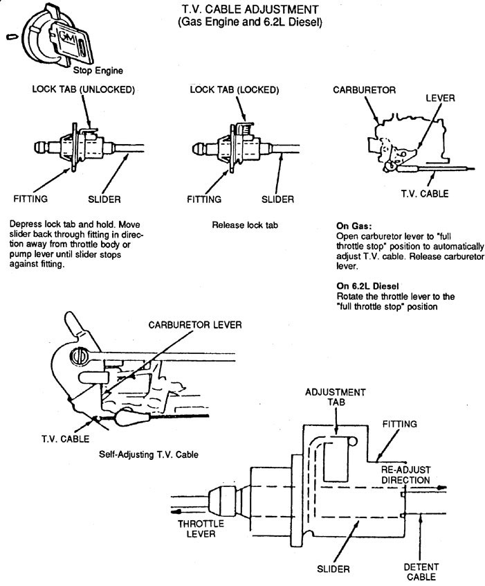
Adjustment procedure (self-adjusting cable)
1. Stop the engine.
2. Depress the adjusting tab and move the slider back through the fitting away from the carburetor until it stops.
3. Release the adjustment tab.
4. Move the throttle linkage to rest against the full throttle stop, then release it.
5. Check the cable to insure that it is not sticking or binding.
6. Road test the vehicle.
7. If the problem still exists, refer to the cable diagnosis section.
SEE DIAGRAM
TV CABLE BRACKET FABRICATION
This section is only for those that do not have a previous TV cable setup, or for those who’s TV cable will not fit into the specifications in the previous pages.
Proper installation and adjustment of the TV cable is the most important aspect of a transmission. Don’t think of it as « just a kick-down cable » – on the nonvacuum-modulated Th700R4 and Th2004R the TV cable controls line pressure, shift points, shift feel, part-throttle downshifts, and detent downshifts! As the accelerator pedal is depressed and the throttle opens, the TV linkage relays the motion to the valve body’s throttle plunger. In stock installations, the geometric relationship between the TV cable and carb throttle shaft bellcrank produces the required TV cable extension (pull) for the transmission to function properly under different degrees of throttle opening. Failure to preserve the correct geometric relationship in custom installations will inevitably lead to early transmission failure.
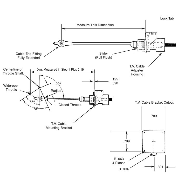
1. Measure your TV cable to establish its particular mounting dimension as follows: First retract the slider by depressing the lock tab, then pull the cable housing until the flats on the slider are flush with the end of the adjuster housing. (To illustrate components in this photo the slider is shown extended, and the lock tab is not fully inserted through the bracket face.)
2. Then, with the slider retracted, fully extend the cable by pulling the cable end fitting out until it stops. Holding the end fitting out, measure the dimension from the face on the adjuster housing that registers with the mounting bracket to the center of the cable and connector.
3. Add 1/16 inch (.190) to the measurement obtained in step 2 – this is the perpendicular measurement from the rear face of the TV cable mounting bracket to the wide-open-throttle position of the TV cable connector pin on the throttle bellcrank.
4. To ensure that the TV mechanism moves in correct proportion to the throttle opening, the TV cable bellcrank must be perpendicular (90 degrees) to the TV cable when the throttle is about a quarter open. The cable connector pin’s mounting location must be established on the throttle bellcrank at a radius of 1.094 to 1,125 inches (also see step 3). If there is no suitable existing hole in the bellcrank, drill a new hole or fabricate a suitable attachment, as required, to properly locate the connector pin.
5. The proper location of the TV cable mounting bracket is determined by the angular and radial position of the TV cable connector pin on the throttle bellcrank. Make sure that other cables and rods will not interfere with the TV cable. Mount the TV cable adjuster housing so that the lock tab is readily accessible.
6. Fabricate the bracket using .090- to .125-inch sheet metal to these housing cutout dimensions. If thicker stock is used, a chamfer is required on two sides of the cable mounting cutout to allow the lock tabs to expand properly. The adjuster requires approximately 18 pounds pull to ratchet out, so make the bracket as rigid as possible.
SEE DIAGRAM